Quinton Kirsch
EF0
Figured here would be a better place than ever to share.
My friends and I have been working on an up and coming research project studying barometric pressure in supercell thunderstorms, tornadic and non-tornadic. Figured I would share what I had got going thus far on my part since we are to a point where the preliminary designs are out of the way and our ducks are in a row (mostly.) We've really not been public about any of our work because other obligations had taken priority and just generally a slew of other things that I hadn’t accounted for. We’re just out of high school. I got out last January and my partner graduates As you can imagine not having adequate income for something like this is difficult and especially so when you’ve got a timeline you’re trying to go by. Despite this we’ve still managed and plan on our debut come 2026.
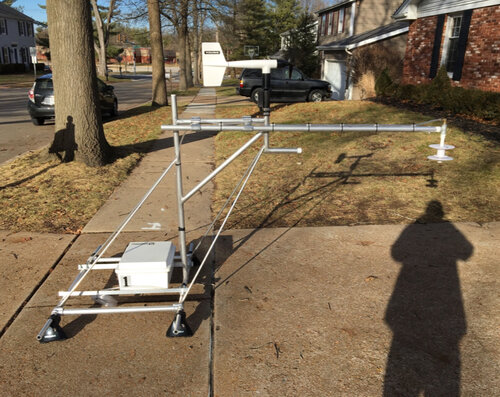
We have plans to use three mobile mesonets, two of the conventional rack style as pictured below and one built specifically on a 2009 Subaru Outback with a similar design to UNL’s and CSWR now FARM’s MMs.
I had put the J-Tube on the rack as a placeholder until we got the U-Tubes. Now obviously at that point I didn’t have data loggers or anything wired up so the whole setup was one big placeholder. But alas it served its purpose. And of course my obligatory disclaimer: if you are reading this and have plans to do mobile obs, do not use the J-Tube, please consult Sean Waugh’s multiple documents regarding the U-Tube and how to construct and assemble them.
First time getting it on my vehicle. (Yes I drove a Prius during this period. I’d like to believe I’m the first to drive an instrumented Prius. Though EC has racks on their older Priuses but we’ll ignore that because it isn’t America.)
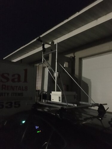
Putting this disaster atop my vehicle just about halved my gas mileage so beware to anyone that wants to do something similar
Something else to note were the obvious design flaws that proved to be problematic later on during the life of this thing. Notably one being the inability to adjust the rear supports, don’t ask why I went that way with design. Perhaps it was convenience?. Certainly not having that “feature” on then final racks.
Pics from a run I did traveling up to see a buddy in Wisconsin. (I'm from St. Louis.) Obviously nothing was hooked up, this was the “look parents it didn’t fall off for more than 1000 miles you can trust me with this thing” test. Taken January of this year.
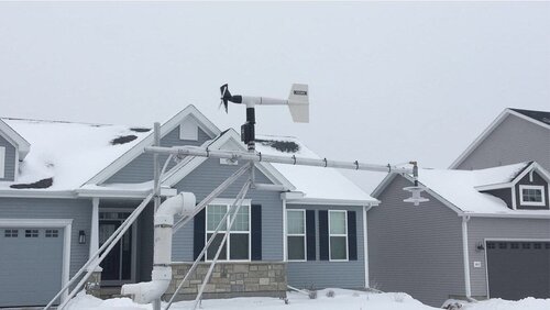 You can see the hoar frost clearly on the anemometer and quad plate in this one.
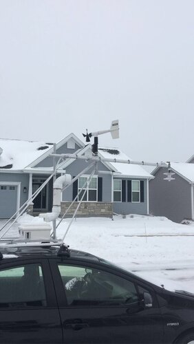
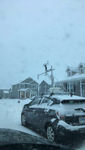
Picture after I had taken it off my vehicle to be put into storage to await the next phase of our project.
The technical stuff:
Anemometer is an R. M. Young 05103 wind monitor. Vehicle heading will be derived using an R. M. Young 32500 electronic compass. Positioning will be computed using a Garmin GPS-16X-HVS GPS receiver. Temperature/humidity will be measured using a Vaisala HMP155A. Fast response temperature will be measured using Apogee Instruments ST-110’s. The instrumented Subaru (as we have “affectionately” named it) will only use one HMP155A and ST-110. My two racks will accommodate the U-Tube and R. M. Young 43408 aspirated radiation shield housing the ST-110. U-Tube housing both HMP and ST sensors.
The theoretical goal in using both shield styles is to achieve accurate temperature measurements in both high precipitation and high solar radiation environments with both shields collocated on the rack.
For those that don’t know, the use of a second, faster response temperature sensor is imperative to mitigate measurement gradient dampening when sampling an environment. (I believe Sherman Fredrickson said something about that with Waugh in his U-Tube publication.) Basically what this is is the smoothing of observed reading because the sensor doesn’t have a fast enough time constant. Time constant essentially being the time I takes for any sensor to make a ~63% step change in reading from the original observation. From what I understand. I encourage anyone reading this to google and come up with way more info than I would know for a deeper understanding.
Barometric pressure is measured using an R. M. Young 61402 coupled with a Nishiyama & Bedard quad plate pressure port extended out above the windshield to negate turbulence effects from the vehicle. MSL pressure is derived using GPS elevation and current obs using whatever hyposmetric equation variant that gets you sea level pressure. Obviously this setup has yet to be tested but given the NSSL uses a similar system it should hopefully prove to be adequate for our use case. Though a publication they made trying to validate pressure measurements suggested that GPS elevation data was finicky and that there needed to be work done on that system. Time will tell. Data collection will be done using a Campbell Scientific CR6-WIFI data logger.
Didn’t expect this to turn into a whole thing but here we are. I plan on sending updates here when we get things going again in the coming months. All in all I’d say it was an important first step in this long process of “research” all in the same of science.
Cheers,
Quinton
My friends and I have been working on an up and coming research project studying barometric pressure in supercell thunderstorms, tornadic and non-tornadic. Figured I would share what I had got going thus far on my part since we are to a point where the preliminary designs are out of the way and our ducks are in a row (mostly.) We've really not been public about any of our work because other obligations had taken priority and just generally a slew of other things that I hadn’t accounted for. We’re just out of high school. I got out last January and my partner graduates As you can imagine not having adequate income for something like this is difficult and especially so when you’ve got a timeline you’re trying to go by. Despite this we’ve still managed and plan on our debut come 2026.
We have plans to use three mobile mesonets, two of the conventional rack style as pictured below and one built specifically on a 2009 Subaru Outback with a similar design to UNL’s and CSWR now FARM’s MMs.
I had put the J-Tube on the rack as a placeholder until we got the U-Tubes. Now obviously at that point I didn’t have data loggers or anything wired up so the whole setup was one big placeholder. But alas it served its purpose. And of course my obligatory disclaimer: if you are reading this and have plans to do mobile obs, do not use the J-Tube, please consult Sean Waugh’s multiple documents regarding the U-Tube and how to construct and assemble them.
First time getting it on my vehicle. (Yes I drove a Prius during this period. I’d like to believe I’m the first to drive an instrumented Prius. Though EC has racks on their older Priuses but we’ll ignore that because it isn’t America.)

Putting this disaster atop my vehicle just about halved my gas mileage so beware to anyone that wants to do something similar
Something else to note were the obvious design flaws that proved to be problematic later on during the life of this thing. Notably one being the inability to adjust the rear supports, don’t ask why I went that way with design. Perhaps it was convenience?. Certainly not having that “feature” on then final racks.
Pics from a run I did traveling up to see a buddy in Wisconsin. (I'm from St. Louis.) Obviously nothing was hooked up, this was the “look parents it didn’t fall off for more than 1000 miles you can trust me with this thing” test. Taken January of this year.
 You can see the hoar frost clearly on the anemometer and quad plate in this one.

Picture after I had taken it off my vehicle to be put into storage to await the next phase of our project.

The technical stuff:
Anemometer is an R. M. Young 05103 wind monitor. Vehicle heading will be derived using an R. M. Young 32500 electronic compass. Positioning will be computed using a Garmin GPS-16X-HVS GPS receiver. Temperature/humidity will be measured using a Vaisala HMP155A. Fast response temperature will be measured using Apogee Instruments ST-110’s. The instrumented Subaru (as we have “affectionately” named it) will only use one HMP155A and ST-110. My two racks will accommodate the U-Tube and R. M. Young 43408 aspirated radiation shield housing the ST-110. U-Tube housing both HMP and ST sensors.
The theoretical goal in using both shield styles is to achieve accurate temperature measurements in both high precipitation and high solar radiation environments with both shields collocated on the rack.
For those that don’t know, the use of a second, faster response temperature sensor is imperative to mitigate measurement gradient dampening when sampling an environment. (I believe Sherman Fredrickson said something about that with Waugh in his U-Tube publication.) Basically what this is is the smoothing of observed reading because the sensor doesn’t have a fast enough time constant. Time constant essentially being the time I takes for any sensor to make a ~63% step change in reading from the original observation. From what I understand. I encourage anyone reading this to google and come up with way more info than I would know for a deeper understanding.
Barometric pressure is measured using an R. M. Young 61402 coupled with a Nishiyama & Bedard quad plate pressure port extended out above the windshield to negate turbulence effects from the vehicle. MSL pressure is derived using GPS elevation and current obs using whatever hyposmetric equation variant that gets you sea level pressure. Obviously this setup has yet to be tested but given the NSSL uses a similar system it should hopefully prove to be adequate for our use case. Though a publication they made trying to validate pressure measurements suggested that GPS elevation data was finicky and that there needed to be work done on that system. Time will tell. Data collection will be done using a Campbell Scientific CR6-WIFI data logger.
Didn’t expect this to turn into a whole thing but here we are. I plan on sending updates here when we get things going again in the coming months. All in all I’d say it was an important first step in this long process of “research” all in the same of science.
Cheers,
Quinton
Last edited:
